久しぶりにスーパーファミコンを引っ張り出してきたら、コンポジット(RCAの黄端子)、S端子ともに、映像の同期が取れないような感じで、正しく映らなくなっていました。(肝心の、乱れた映像の写真は撮っていなかった……)
インターネットの知見を調べてみると、映像出力端の電解コンデンサが容量抜けしやすいようで、ここ数年でいくつかの症例が上がっていることがわかりました。せっかくなら、他の電解コンデンサも含めて、一斉に交換しておくことにしました。
Super Famicom is the Japanese version of SNES. A few days ago, as I turned it on for the first time in years, I found that the video signal seemed not vertically-synchronized properly.
Thanks to the wisdoms on the internet, I found several articles reporting the dry-up case of the electrolytic capacitors placed just before the video signal output. Then, I decided to replace all capacitors of such types, following the basic theory: "When one capacitor dries up, replace all."
分解
Disassembling
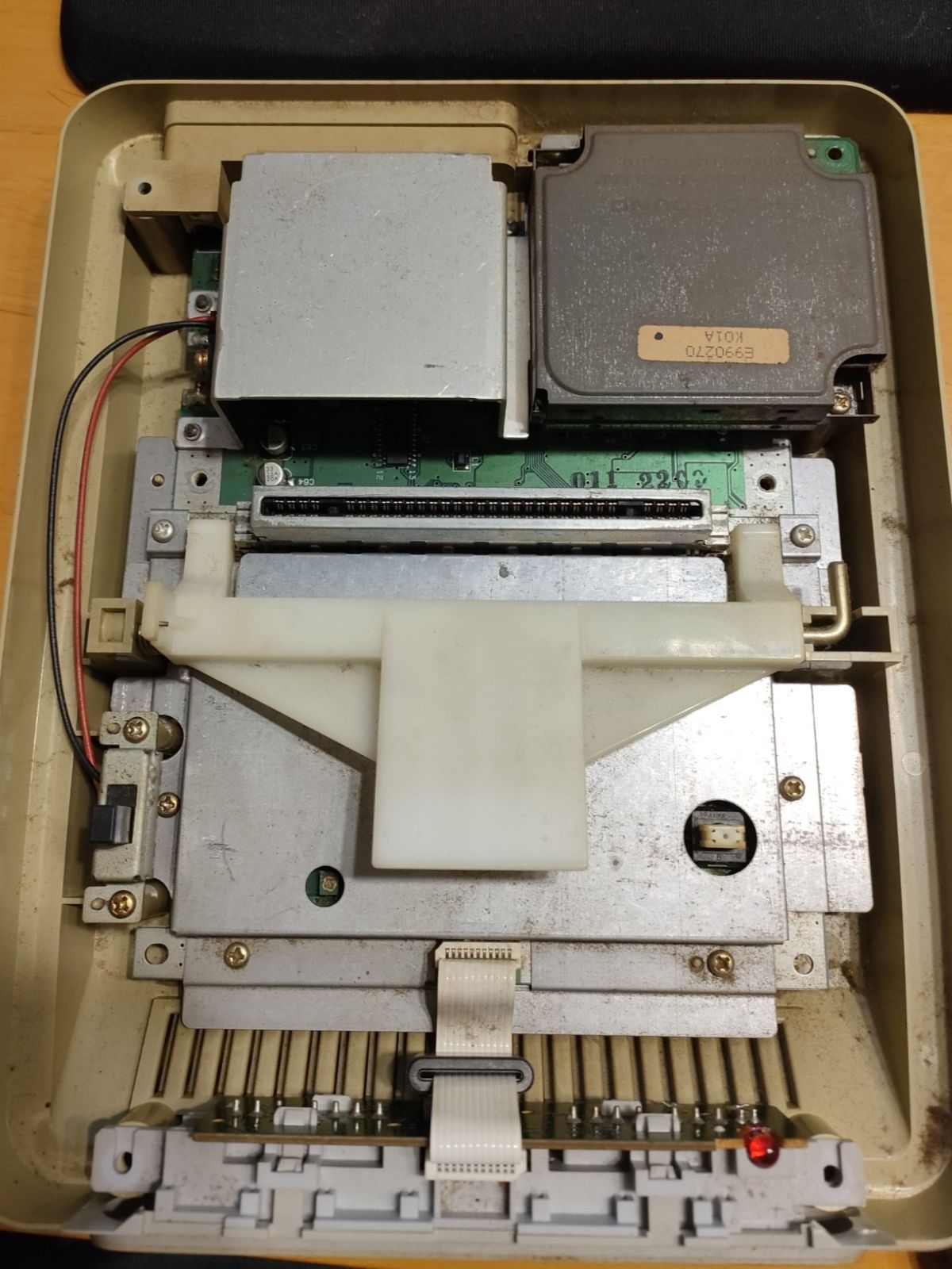
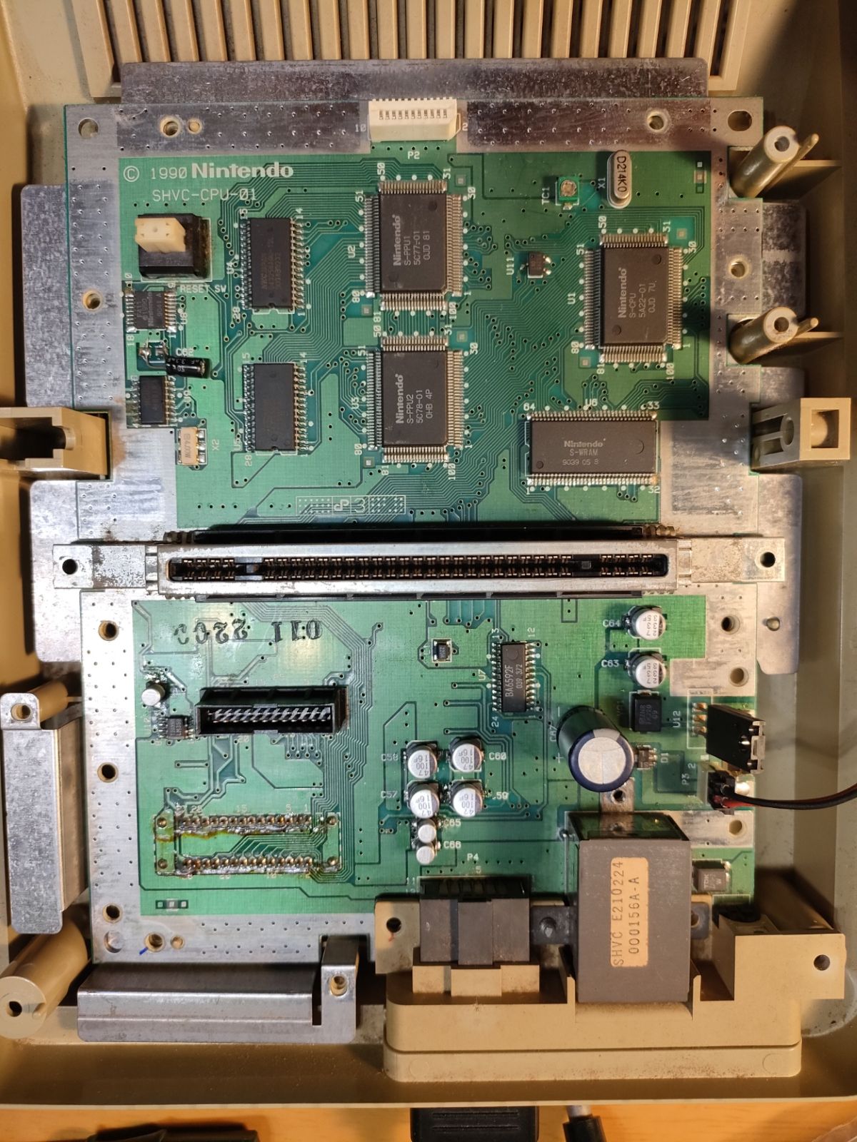
スーパーファミコンのケースを開けるには、(多くのサイトで言及されているように)特殊ドライバー「DTC-27」が必要です。これを使って上カバーを外すと、下の写真のように内部の部品が見えます。前面の回路基板はフレキシブルケーブルでマザーボードに接続されていますが、ケーブルを上に引っ張ることで簡単に取り外すことができます。
中央にある大きなプラスチック部品は、カセットを取り出す「EJECT」の機構です。金属軸・バネと共にに取り外しておきます。
First of all, we need to use a special screw driver "DTC-27" to open the outer case. We can see the inner parts like the picture below just after removing the upper cover. The front-side circuit board is connected to the mother board by a flexible cable, which we can easily disconnect by pulling the cable (not the connector) up. Also we need to remove the "Eject" mechanism to access the circuit board, which is the large plastic part in the middle combined with a metal axis and a spring.
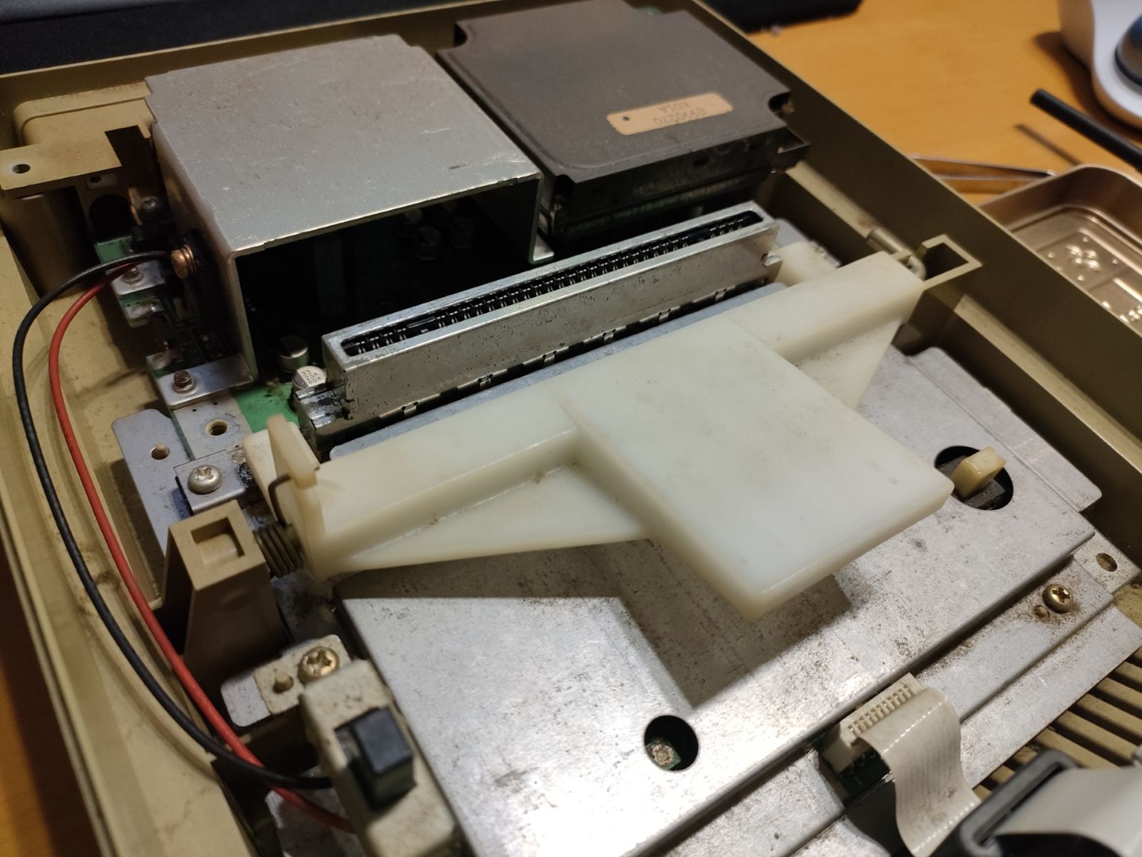
右上の黒い四角い箱はサウンドモジュールです。マザーボードにはコネクタで接続されており、ネジを外した後、真上に引き抜いて取り外せます。さらに、電源スイッチ、中央の大きな金属板を取り外し、ネジを外せば、マザーボードがケースから完全に外れます。
なお、ここまでで、3種類のネジがありますので、区別しておきましょう(短いネジ、長いネジ、外側ケース用の特殊ネジ)。このあとさらに、別の種類のネジとして、三端子レギュレーターを金属ケースに取り付けているネジ(下の写真を参照)と、金属ケース自体をマザーボードに取り付けているネジがあります。
The black square box on the upper-right corner is the sound module. This can be also easily removed by pulling it up after removing screws. After removing the power switch, the large metal plate and several screws, we can retrieve the mother board independently.
Please note: Up to this moment, three different types of screws have appeared: shorter one, longer one, special screws for the outer case. In addition, there are two more types of screws: one is used to attach a power regulator onto a metal casing (see the photo below), and the other type of screws is to fix the metal casing onto the mother board.

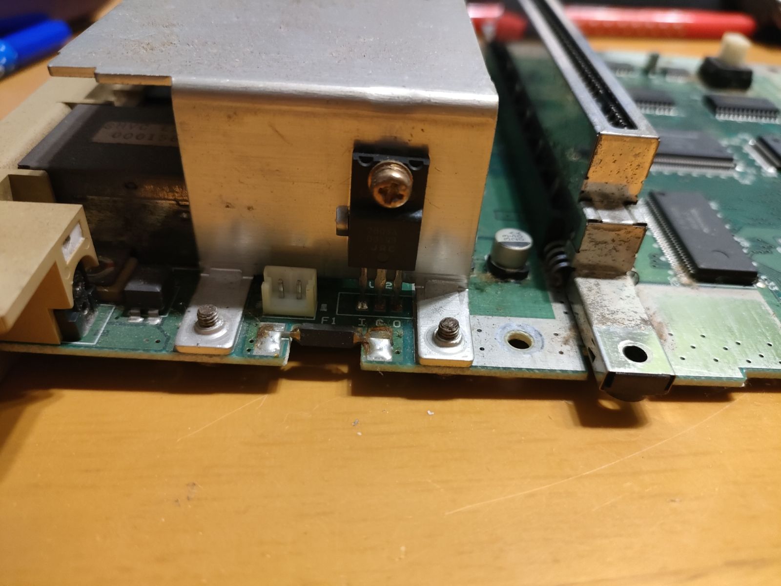
この金属ケースの下に、今回交換する電解コンデンサがあります。
The capacitors to replace today are implemented under the metal casing.
電源用コンデンサ
Capacitors for Power Regulation
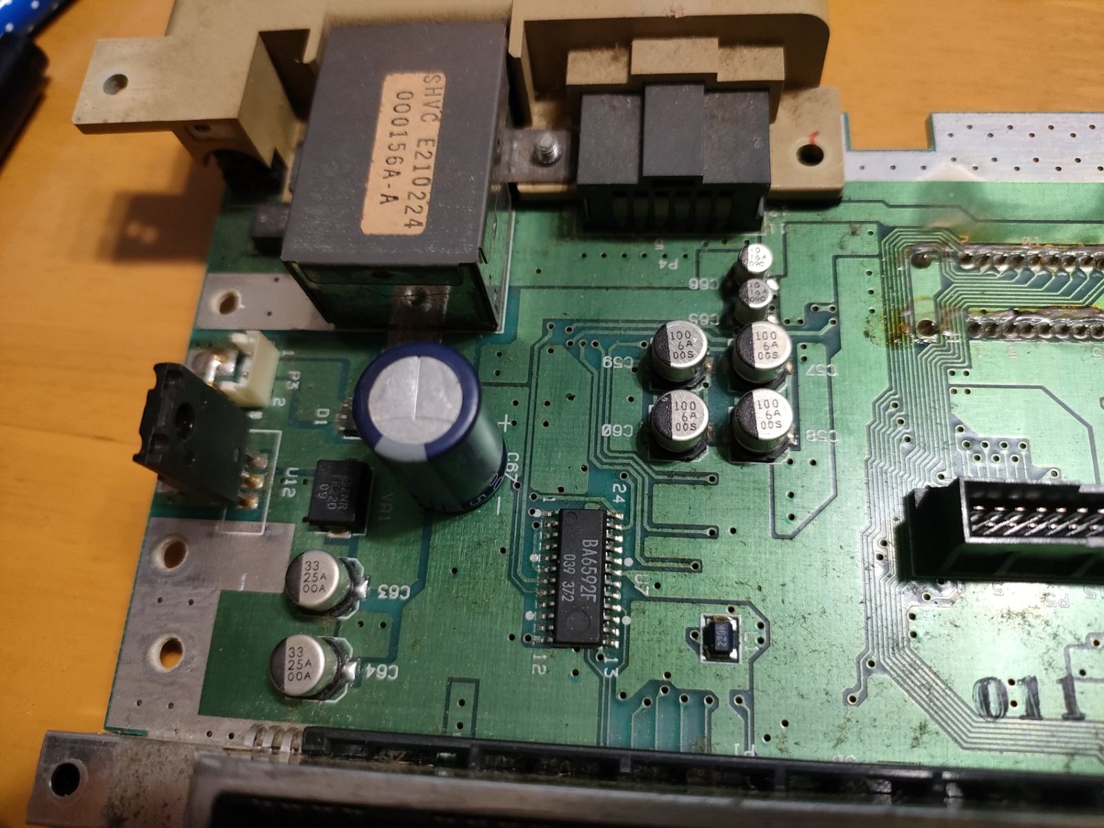
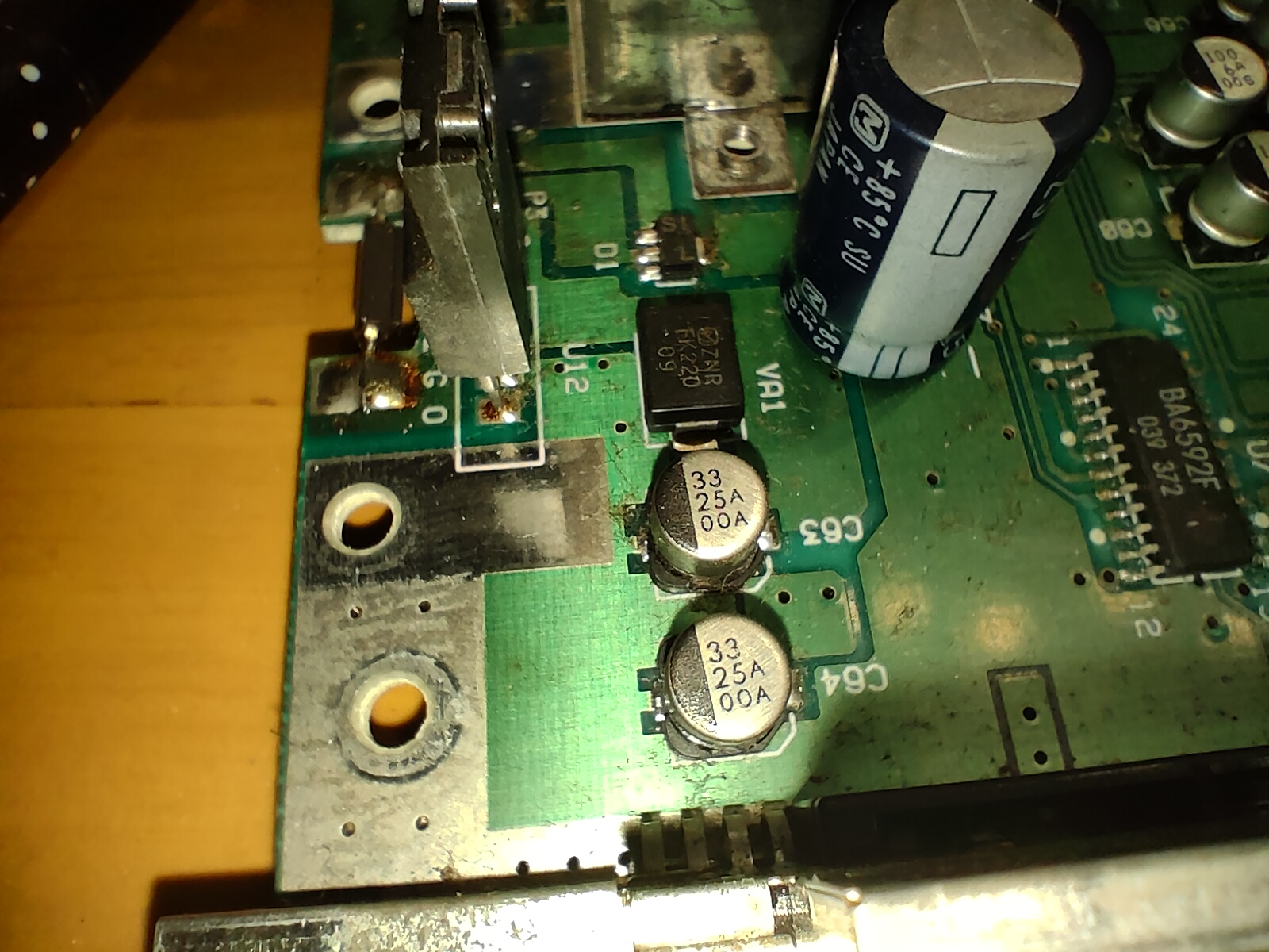
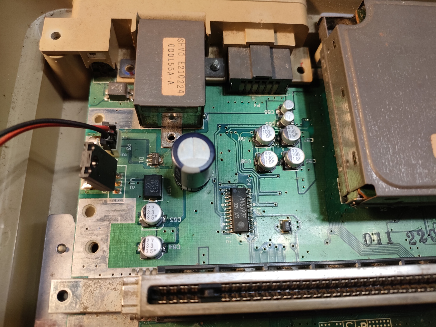
C63とC64(33μF 25V)は、電源ラインとGND間のバイパスコンデンサです。それぞれ電源レギュレータの前と後に配置されています。
なお、今回は、平滑コンデンサ(C67:1000μF 25V)は交換しませんでした。
C63 and C64, 33μF, 25V, are bypassing between the power supply line and GND. before and after the power regulator respectively.
I did not replace the large one (C67: 1000μF, 25V) this time.
信号出力用コンデンサ
Capacitors for Video/Audio Output
C57~C60(100μF、6V(or 16V?))は、ビデオ信号出力用のカップリングコンデンサです。なお、C57とC58は並列接続二接続されているだけのようです(C59とC60も同様です)。
C57 - C60, 100μF 6V (or 16V?), are coupling capacitors for video signal output. C57 and C58 look like just a parallel connection (and so do C59 and C60.)
C65・C66(10μF 16V)は、オーディオ出力のカップリングコンデンサです。
C65 and C66, 10μF 16V, are for the audio signal output.

オーディオミキサのオフセット電圧用コンデンサ
A Capacitor for Audio Mixer's Offcet Voltage
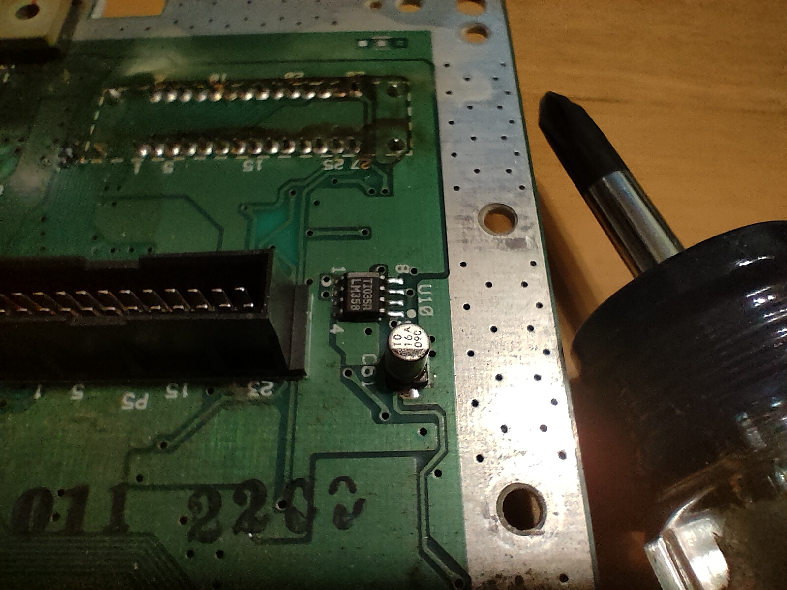
C61(10μF 16V) は、オーディオミキサーの入力オフセット電圧を安定させるためのバイパスコンデンサです。
C61, 10μF 16V, is another bypass capacitor around the audio mixer in order to stabilize the input offset voltage.
リセットスイッチ付近のコンデンサ
A Capacitor near the Reset Button
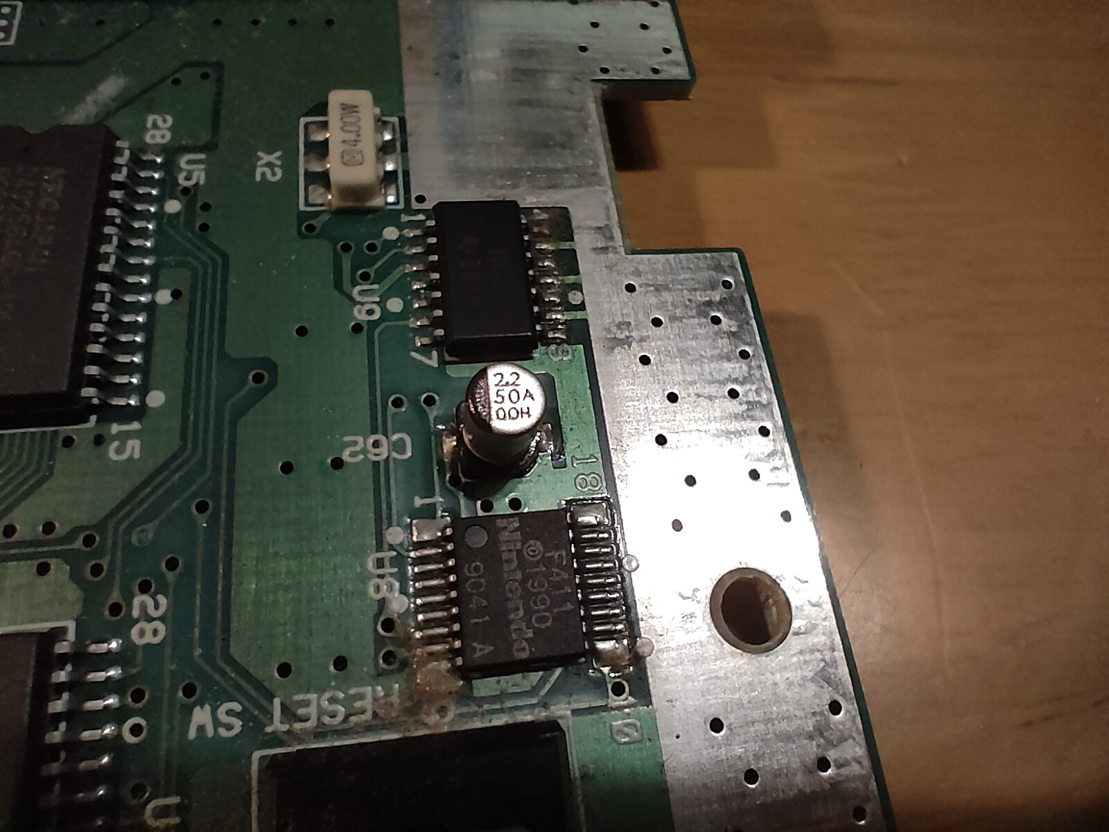
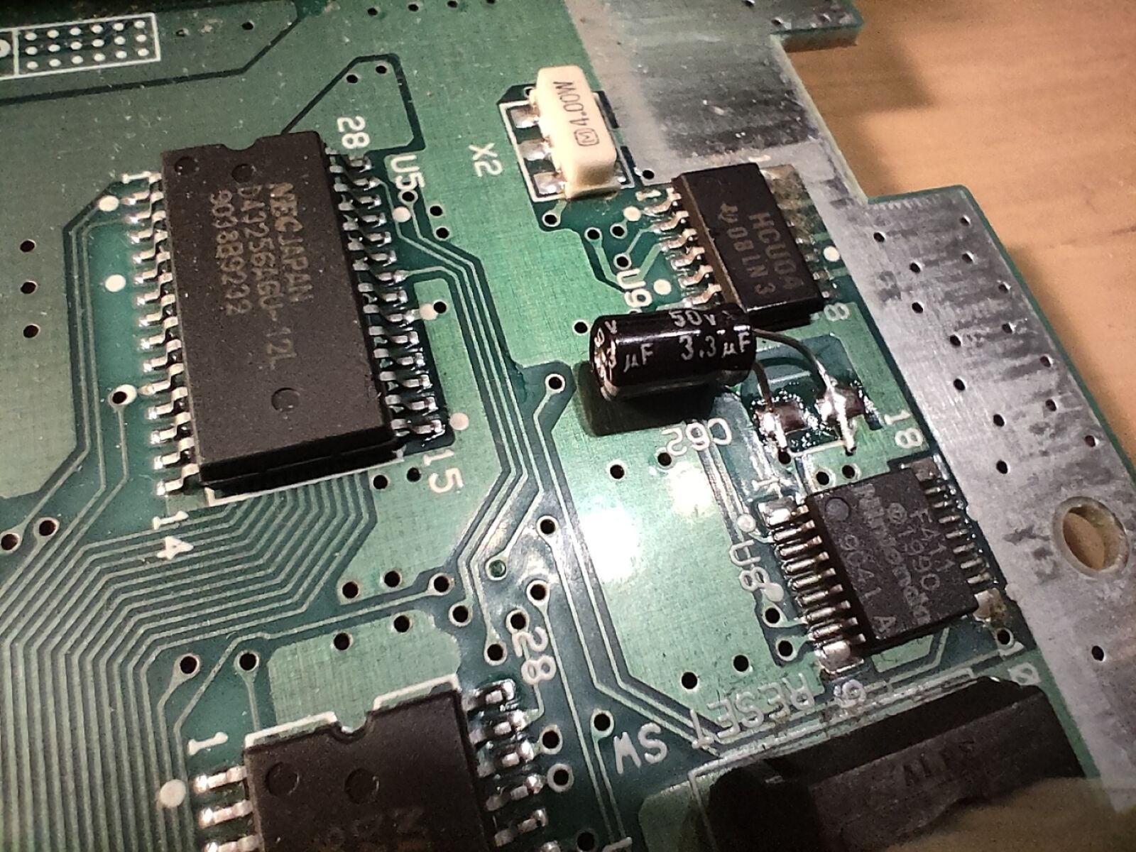
C62(2.2μF 50V?)は、リセットボタンのチャタリングを除去するためのものと思われます。なお、回路図や既存の記事を基に買い物リストを作成する際、このコンデンサの存在を見落としたため、手持ちのコンデンサ(3.3μF 50V)へ交換しました。今のところ、多分問題なく動いています。
C62, 2.2μF 50V?, is presumably to remove the chattering of the reset button. I missed this one when creating the shopping list, so I replaced it with a 3.3μF 50V capacitor from my stock instead.
交換後……
After all replacement...

(Well, I was so lazy that I did not take a screenshot of the video output before the replacement!)